How to Prepare a Technical Drawing for CNC Machining Quotation
Propart

To obtain an accurate CNC machining quotation, it is crucial to provide a precisely prepared technical drawing. This document should contain all necessary information that will allow us to properly estimate the time, materials, and technological processes required to complete the order.
Below are the aspects to consider when preparing a technical drawing for a CNC machining quotation.
Accepted File Formats for CNC Technical Drawings
When preparing a technical drawing for CNC machining quotation, it is essential to choose the appropriate file format. The formats we accept are:
- DXF (Drawing Exchange Format) – commonly used in laser cutting, water cutting, and plasma cutting.
- DWG (AutoCAD format) – primarily used in CAD design.
- STEP (Standard for the Exchange of Product Data) - standard 3D format for CNC machining, milling, and turning. We also accept IGES (IGS) and STL files.
How to Save a Technical Drawing for CNC Machining
The drawing should be saved in one of the above formats, ensuring the file version is compatible with the software used by the manufacturer. It is advisable to ensure the file does not contain unnecessary layers, blocks, or auxiliary elements.
DXF, DWG, STEP – Which Format to Choose for CNC?
- DXF/DWG – suitable for 2D drawings.
- STEP – recommended for 3D machining, such as CNC milling and turning, as it retains solid model data.
- IGES (IGS) – older 3D format, sometimes used instead of STEP.
- STL – format used in 3D printing.
Scale and Dimensions
It is best to use a 1:1 scale to avoid errors in dimension interpretation. If the scale is different, this should be clearly indicated.
Dimensioning in Technical Drawings – Rules for CNC
- All critical dimensions should be clearly defined.
- It is recommended to provide external, internal, and hole dimensions.
- Use millimeter units (mm), unless otherwise specified.
- The drawing should include symmetry axes and thread and chamfer markings.
Dimensional Tolerances in CNC Technical Drawings
Dimensional tolerances should be clearly specified, especially for parts requiring high precision. It is advisable to use:
- General tolerances according to ISO 2768.
- Geometrical tolerances, such as straightness, parallelism, perpendicularity.
- Hole and shaft fits according to ISO 286.
Additional Information
Material Description in the Technical Drawing for CNC - Even if the material is provided by the customer for machining, information about the material will be necessary at this stage to select the proper parameters and cutting tools.
The drawing should specify:
- Material type (e.g., stainless steel, aluminium, plastic)
- Material grades according to standards (e.g., S235, 7075-T6)
- Indications for any heat or surface treatment.
Surface Roughness Designation in the Technical Drawing
Surfaces that require a specific roughness should have the corresponding markings according to ISO 1302. Common roughness values are:
- Ra 0.8 – for precision parts.
- Ra 3.2 – for standard elements.
- Ra 6.3 and higher – for surfaces that do not require high precision.
If the part requires welding or additional operations, appropriate symbols according to ISO 2553 should be included. Besides welding, there may be markings for hardening, galvanic coatings, or painting.
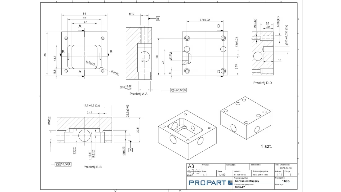
Example Technical Drawing for CNC Machining Quotation
The drawing should include:
- Part name and number.
- Scale and units.
- Exact dimensions and tolerances.
- Material information.
- Additional technological requirements.
Sample Technical Drawing for CNC Milling
A well-prepared drawing for CNC milling should include views from different perspectives, cross-sections, and precise hole markings. It is also helpful to include a table with hole, thread data, and a list of operations.
Checklist – Technical Drawing Ready for CNC Quotation
- Has the drawing been saved in an accepted format (DXF, DWG, STEP)?
- Is the scale 1:1?
- Are all dimensions clearly defined?
- Have dimensional tolerances been considered?
- Has the material type been provided?
- Has surface roughness been marked?
- Have necessary technological markings (welding, threads, etc.) been added?
- Is the drawing clear and unambiguous?
- Are additional machining instructions included?
A well-prepared technical drawing enables accurate quotation and efficient execution of the CNC order, reducing production time and eliminating potential errors arising from documentation inconsistencies.
